

UFIT viscosity systems are built from standardized, modular building blocks that can be configured for laboratory environments.
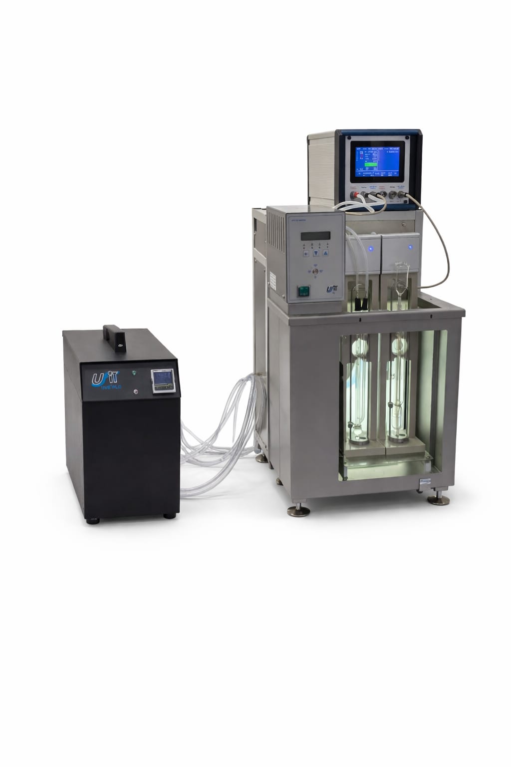
Typical UFIT viscosity system layout
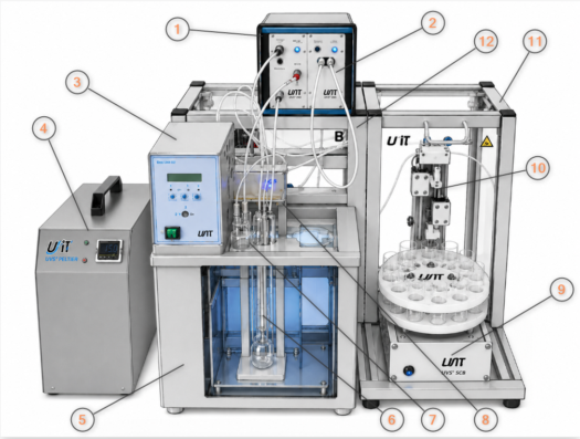
A typical system includes:
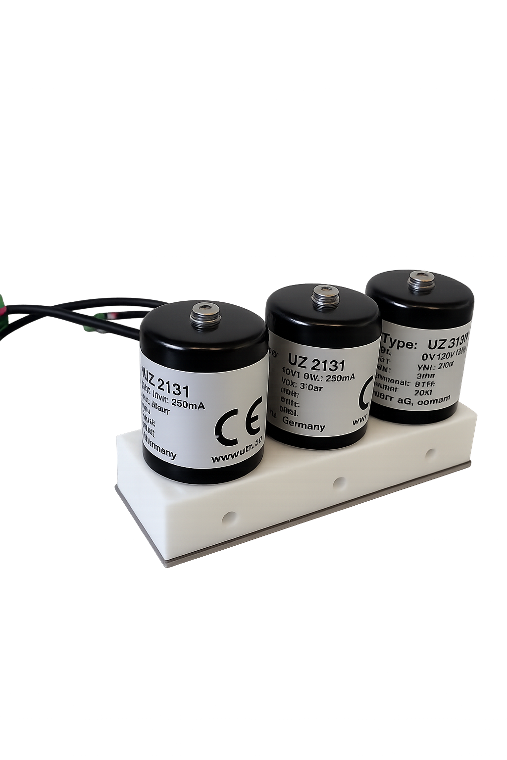
- UVS MD, measurement device for precise flow time measurement and control the flow inside the viscometer.
- UVS Drain, vacuum pump which discharges the samples and solvents (option)
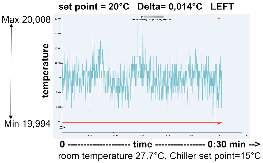
- UVS TB2, constant temperature bath controller to condition the sample at a defined and stable temperature.
- UVS Chiller, cooling device to receive precise temperature in the bath for measurements below 35°C
- UVS TB2, constant temperature bath out of stainless steel with window to see what happens
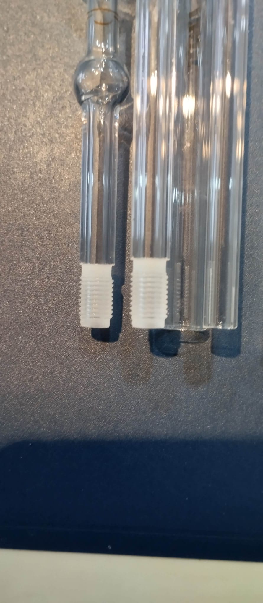
- Glass viscometer, the heart of the measurement, calibrated for precise flow control and stable measurement conditions.
- Safety bottle, safety to avoid any risk that sample is sucked into measurement device
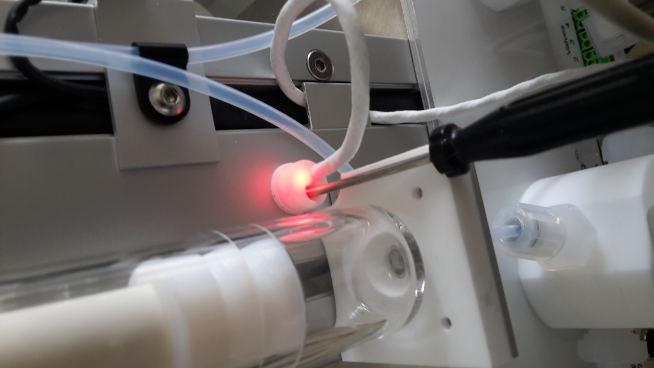
- UVS LB, stand with light barriers for the automated and exact meniscus detection of the sample, containing a third safety light barrier
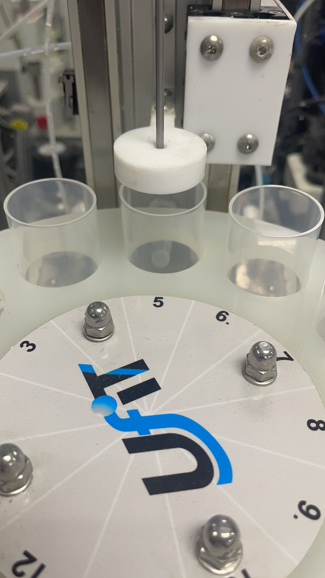
- SC8, sample changer, the high end solution of automation, multiple measurements in sequence for one or two channels (option)
- transfer unit, part of the sample changer, responsible for the transfer of the liquids
- UZ2406, rack for the SC8 additional protection against hazards
- UZ2405, rack with integrated backlight illumination, ensuring optimal positioning of the measurement device
Further components (not part of the picture):
- Waste system, waste bottle with sensor for bottle full detection. Sample transport via vacuum to the explosion protected waste bottle.
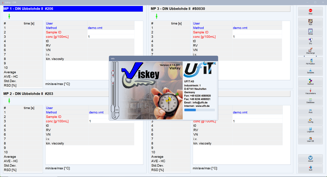
- UVS Viskey, software which controls the measurements and automation for up to 8 channels at same time.
- Data interface, data viewer for all results and export interface for integration into LIMS, or laboratory software.
Key UFIT design principles

Trusted suppliers for sensors, control, and automation

In addition to the modular expansion of the number of channels and the level of automation for each individual measurement channel, customized adaptations can also be implemented.
SC8 sample changer:
The sample changer can be configured for customer-specific sample bottles, with a focus on achieving the maximum possible number of positions on the sample tray.
Sample detection:
Automatic detection of the appropriate measurement method based on the customer-specific sample designation.
Results export:
Automatic export of data in a customer-specific format.
Waste system:
Custom adaptation of the waste disposal system to the customer’s on-site conditions.
Physical system configuration:
Flexible module arrangement to suit specific on-site requirements.
UFIT systems are based on the capillary measurement principle: a defined volume of fluid is driven through a precisely manufactured capillary under controlled conditions, and the resulting flow behavior is used to determine viscosity.
On the detailed Measurement Principle page, you will find:
- A step-by-step explanation of the physical principle and flow behavior.
- An overview of the measurement setup and core components.
- How relative and absolute viscosity are determined.
- Factors influencing calibration, accuracy, and stability.
- The main advantages of the capillary method compared to alternative approaches.
Choose your next step
You now have an overview of the UFIT viscosity measurement technology and system design. The next step is to translate this into a concrete solution for your laboratory or process.
You can either explore our standard products and systems in the shop, or discuss a customized configuration with our engineering team.